Articles / Case Studies
-
-
Evaluating Environmental Protection Requirements For Instrument Enclosures
 1. Introduction
2. Insulation Blankets
• Technical Advantages
• Technical Disadvantages
• Commercial Advantages
• Commercial Disadvantages
3. Traditional (Rigid) Enclosures
• Technical Advantages
• Technical Disadvantages
• Commercial Advantages
• Commercial Disadvantages
4. Contact Heated Body Enclosures and Contact Heated Full Enclosures
• Technical Advantages
• Technical Disadvantages
• Commercial Advantages
• Commercial Disadvantages
5. Conclusions
6. Sources and References
1. Introduction
The demand for natural resources continues to grow around the world. With so many emerging economies and increased demand from traditional markets, the need to utilize previously untapped resources becomes a necessity. Many of these resources are in areas of the world where the environmental conditions made operating facilities impractical.
Most process industries are heavily dependent on pressure measurement instrumentation for successful operation. Many pressure measurement installations are particularly susceptible to inaccuracy or damage due to the cold environments that these devices are now required to operate in.
For many years the solution to cold weather has been to place pressure transmitters inside an insulated enclosure that contains a space heater, or to use heat trace from the process piping in combination with an insulation blanket.
The use of an insulation blanket (also known as a Soft Pack) is very problematic. Flexible blankets have a tendency to break down over time and lose their insulation value. In addition, repeated installation and removal of these blankets leads to breakage of the retaining clips and an increased risk of the blanket being damaged or lost while not in place.
The use of an insulated and heated enclosure as it has traditionally been designed and installed also creates its own set of problems. The temperature limits of traditional designs are very often unable to meet the demands of today’s environmental specifications. The use of traditional space heaters is also very energy intensive and in many cases leads to more than a gigawatt of additional power that can be consumed in a year. Furthermore the installation of these enclosures requires a great deal of engineering effort and on site labour.
A very effective solution to the problem of cold weather pressure transmitter installations is to use an engineered contact heated enclosure solution. This type of system will include the process connection and isolation manifold, a low power contact heater and an impact resistant, insulated cover. A single manufacturer can design, build and test this system with any manufacturer’s pressure transmitter, ensuring proper operation at the specified design temperature. A further benefit to an engineered solution is that there is no need for “on site design”. The engineered solution relies on standard mounting that can accommodate any valve configuration but will retain a single heater and insulated cover design.
For the purpose of this paper we will focus on remote mounted pressure measurement instruments requiring impulse lines, which include differential pressure flow and are the most common application that requires winterization.
2. Insulation Blankets (Soft Packs)
An insulation blanket for a pressure transmitter consists of a weather and heat resistant fabric, usually a type of Teflon, silicone, or PVC which serves as an outer shell to contain a flexible insulation material that is usually a form of glass wool or ceramic fibre. The insulation blanket material is then cut into multiple pieces and sewn into a form fitting shape that matches the transmitter electronics housing, sensor body and instrument manifold. The blanket is designed to be removable which requires that a latching system of Velcro™ or plastic clips be used to secure the blanket. Heating is generally accomplished by the use of standard heat trace which is most often extended from the process piping and wrapped around the instrument, but can also be incorporated into the material of the insulation blanket.
• Technical Advantages
From a technical standpoint, the use of insulation blankets does have advantages in many circumstances.
• On many projects space and weight concerns are a very large consideration. Insulation blankets allow for an extremely small addition to the footprint of any device that requires winterization. As insulation blankets are custom fit they can easily be tailored to match the exact dimensions of the device.
• In the case that maintenance is required on any device equipped with an insulation blanket, the blanket can be quickly and completely removed in order to allow full access to the device.
• Insulation blankets with incorporated heat trace have the added advantages of installation simplification due to the fact that the device does not require that the heat trace be installed in a separate step, and the heat from the embedded tracing will tend to provide a more even distribution throughout the blanket.
When considering the use of insulation blankets, the technical advantages that insulation blankets can offer are more often conducive to use on large items such as valves, drums or pumps where the use of a rigid enclosure is either impractical or impossible.
• Technical Disadvantages
Despite the appearance of simplicity and efficiency that insulation blankets would seem to offer, in the case of instrumentation winterization the technical disadvantages will tend to culminate in unsatisfactory performance at temperatures that are often well above the original design specifications. There are a number of reasons for the underperformance of insulation blankets.
• The most common problem with insulation blankets is an overall lack of consistent insulation thickness. When insulation blankets are constructed the sewn seams create a point over their length where the glass or ceramic is only a few millimetres thick. This creates a relatively large area for heat to rapidly escape and the resulting cold spot can lead to instrument freeze up.
• Long term durability of insulation blankets is often called into question for several reasons.
o The flexible nature of the blanket allows for compaction and breakdown of the glass or ceramic fibre insulation which the system depends on. Snow buildup, heavy rain, and installation and removal of insulation blankets seem like minor issues, but the cumulative effect is a slow breakdown of the insulation value.
o Long term durability is also called into question when considering the outer jacket material. Numerous factors including low temperature, UV or chemical degradation, or physical damage due normal wear and tear can result in cracks or cuts in the fabric. The resultant water penetration is disastrous for the insulation value and can even result in a heat sink effect where the water soaked insulation results in higher risk of freezing than having no insulation at all.
• Repeated installation and removal of insulation blankets can also create another set of problems. The first is that many blankets require great care to ensure the proper fit is attained. Most manufacturers will use their own technicians to install all blankets. In the course of normal facility operations it is not practical to have manufacturers technicians on site to remove and re-install blankets when required, and even the most competent operations staff cannot be expected to have the same proficiency as a factory trained technician. The second problem, which can often be mitigated through the use of Velcro™, is damage to blanket fasteners. Plastic clips are commonly used and are very susceptible to breakage in cold weather. Either of these problems on their own or a combination can result in the penetration of cold air into the system with disastrous effects on the overall quality of heating.
All of these disadvantages do represent a “worst case scenario” and many steps can be taken to mitigate the associated risks. Operational procedures, physical protection, and careful design selection are all ways to help reduce risks.
• Commercial Advantages
For all of the presented flaws of using insulation blankets there are distinct advantages from the perspective of project costs
• All necessary blankets can be sourced and installed by one manufacturer. The engineering team can combine the required blankets for valves and other custom applications with the instrumentation winterization scope. The manufacturer can simply utilize the drawings provided by the engineering and procurement contractor to design and manufacture every insulation blanket. Expensive engineering effort is avoided to specifically outline each separate winterization application.
• If it is determined later in a project, or after startup that insulation is required in a particular application, it is very simple to provide the installation detail drawing to the blanket manufacturer and have another unit produced with little engineering effort, only a modification to the device data sheet should be required.
The cost effectiveness of having a single manufacturer provide all materials has been proven many times to be advantageous from both an installation cost and warranty perspective.
• Commercial Disadvantages
While cost savings from using a single manufacturer are well proven, there are still drawbacks to using insulation blankets from a commercial perspective.
• Insulation blankets are not inexpensive to produce. While they are less expensive than many types of rigid enclosures each blanket must be designed, cut and sewn for every application. The result is a solution that from a hardware perspective can easily cost as much as certain alternatives.
• On site labour is always an added expense. In order to properly ensure the correct installation of insulation blankets it is required that manufacturer technicians install each blanket. Whether it is done at site or at a fabrication yard the technician charges will always be higher than if winterization can be pre-assembled and installed by technicians already on site.
Project costs are often the object of some of the greatest scrutiny. It can be very advantageous for project engineers and package unit vendors to more closely examine whether apparent cost savings are easily offset but other associated costs.
3. Traditional (Rigid) Enclosures
Traditional enclosures are the most common type of instrument winterization used today. The overall design has remained relatively unchanged for more than 40 years, and is meant to be used in place of insulation blankets or hand built utilidor systems. A traditional enclosure is an insulated rigid box that usually requires a NEMA 4 or 4X rating and is most often constructed of molded glass reinforced polyester that is mounted to a stand near the process taps of the measuring device. Inside the enclosure is a second stand that is used to mount the instrument, and a thermostatically controlled space heater that is sized according to the heating requirements for each individual application. The impulse line(s) must enter through the wall of the enclosure where they are connected to an instrument manifold using tube fittings. The space heater is used to heat up the air inside the enclosure to a predetermined temperature and will generally require a minimum of 150 watts of power for relatively mild temperature application (-20°C) but can use up to 600 watts for harsh climates (-50°C).
• Technical Advantages
The use of traditional enclosures does have a number of advantages when compared to utilidor and insulation blanket type systems.
• An insulated traditional enclosure has a distinct advantage over other systems because of the universal nature of the design. By using a generic box the only concern is whether it will be large enough to accommodate the transmitters that are to be installed inside. Most manufacturers offer multiple sizes to ensure that they will be able to accommodate single or multiple transmitters.
• A second advantage of the universal nature of the design is that engineers can use components from multiple vendors. Brand A, or Brand B of transmitter combined with Brand C or D of manifold is of no consequence as the enclosure will be large enough to accommodate any combination of equipment that is required.
• Traditional enclosures also eliminate the problem of weather penetration. Because traditional enclosures often carry a NEMA 3, 4 or 4X rating they eliminate the problem faced by insulation blankets of weather penetration. The rigid design also helps to mitigate long term durability questions, as the enclosure will not bend and flex and prevents the degradation of the insulation material.
• By creating what is now a self-contained system that is designed to be opened and closed whenever required, the concern of installation and removal of the winterization is no longer an issue. The traditional enclosure will utilize either a hinged or removable cover with durable metal latches that will allow operations and maintenance to access the device inside with no real concern for ensuring correct re-installation.
The overall technical advantages of traditional enclosure systems have led to their widespread use in virtually all industries where winterization is a concern. The universal nature of the design has also allowed on site technicians to simply order the required components for new winterized application and be almost completely certain of a successful installation.
• Technical Disadvantages
Despite more than 40 years of use and widespread acceptance by nearly all sectors of industry, there are disadvantages to a traditional enclosure system. These issues are often not readily apparent and have often simply been accepted because of a lack of alternatives.
• The use of a space heater powered by electricity or in some cases steam is the accepted practice for heating enclosures. While this system does accomplish its goal, it creates many small concerns that need to be addressed on a case by case basis.
o Placement of the heater within the enclosure can cause several different issues. In the case of mounting the heater on the side of an enclosure a temperature differential can be created in differential pressure application that will cause an error in readings. Additionally, circumstances may require that a heater be mounted in a relatively high point inside the enclosure, the result of this is very often a large amount of cold air in the bottom of the enclosure which can result in the freezing of the instrument. It is also very difficult to place the heater where there is no risk of a technician or operations staff burning themselves when contacting the heater, and a manual disconnect is often required for health and safety purposes.
o Space heaters require the transfer of heat to be accomplished through heating of air. Air is a natural insulator and as such has very poor conduction qualities. It takes a great deal of energy to warm the air inside the enclosure of which very little is transferred into the sensor body of the transmitter often resulting in a much different temperature inside the sensor compared to the air inside the enclosure, and in some cases enough to present a risk of freezing.
o The dependence on maintaining air temperature also requires an enclosure to have a seal that prevents air from escaping. While this may seem like an advantage, it does create the problem of trapping potentially dangerous gases. When conducting an area gas test prior to executing hot work this must be taken into account and written procedures developed and followed to prevent incidents.
o Because of the dependence on the high air temperature, the outer surface of the enclosure will also act as a heat sink to the air or to any snow buildup resulting in very high power consumption in harsh weather conditions.
o If any maintenance is required on a transmitter in cold conditions the opening of the enclosure will result in the complete loss of all conduction of heat. The result is a very short period of time that a technician is able to access a device before the risk of freezing becomes a concern. Additionally it will require significant time to reheat the air once the enclosure is put back into service.
o When using air as a heating medium, maintaining the temperature of the air inside the enclosure requires the use of a thermostat. It is very difficult to install a high quality temperature switch inside an enclosure due to size constraints, and cost. The result is that a low cost pre-set thermostat that cannot be adjusted is required. The typical setting for this switch will be 10°C, but due to the high deadband of most small thermostats the result is often temperature swings of more than 20°C in a very short period of time, which can result in measurement error and risk of freezing if there is any drift in the switch calibration.
• The universal design of the traditional enclosure does create another set of potential issues.
o The enclosure is constructed of a molded material that has no entry points in it for instrument tubing or electrical connections. Holes must be manually drilled to accommodate these entries. If there are any errors made the entire enclosure is generally replaced.
o The NEMA rating is invalidated due to required modifications of the structure that are not evaluated by any rating agency.
o Every entry point must be resealed which requires the use of specialized components such as a tubing entry boot and specialized plates allowing the use of otherwise standard electrical components
o Once these entry points are created it is still a very time consuming task to install the components. In particular, the instrument tube(s) must pass through the wall of the enclosure and then be bent into a specific line in order to properly seat within the tube fitting(s). This not only extremely difficult and time consuming to ensure the proper tube fitting installation, if there are any failures, all of the potential leaks are contained within the enclosure.
o Depending on the enclosure manufacturer, the instrument heat trace for the instrument tubing may or may not be brought all the way inside the enclosure. In the case that it is terminated outside the enclosure there is a large risk of freezing of the tubing at the point where the heat trace is no longer in contact with the tubing, but is still outside the enclosure.
• Traditional enclosures generally follow 2 designs, they will either have a Z split style, or will have a removable cover, both of which require that the enclosure mount onto the top of a pipe stand. This presents 2 problems. The first is that the installation is mechanically weak as it is only secured at one point. Secondly, there will always be a solid bottom that acts as a catch tray. If there are any process leaks, this tray will contain them, and condensation due to temperature changes will also be held. Holding condensation can be detrimental to insulation value, and the process fluid can cause any number of problems, from chemically damaging the enclosure to actually filling the enclosure and damaging the transmitter.
• Most traditional enclosures are manufactured from glass reinforced polyester, which is a relatively hardy material, but does present its own set of challenges. For instance GRP is not an anti-static material which requires for most facilities that an anti-static coating be applied from the factory. Secondly, GRP becomes brittle once the temperature reaches below -40°C. Normal service can easily result in impacts that are capable of causing damage to GRP, and in particular, falling ice is a risk for traditional enclosures in cold climates.
While overall, traditional enclosures do offer a sound winterization solution and definite advantages over insulation blankets or hand built systems there are many concerns which must be addressed for every specific application.
• Commercial Advantages
Traditional enclosures, despite many challenges, do present many commercial advantages for project execution
• A traditional enclosure can be pre-assembled by qualified technicians in a commercial facility. The advantage of doing this is to take as much on-site labour out of the project as possible. Electrical conduit and related components can all be preinstalled and certified by the appropriate standards inspectors prior to being delivered to site.
• The reduction in risk to the project of having all small components such as nuts and bolts, tube fittings, and tags, as well as the transmitters and manifolds all managed by one single party helps to ensure the smooth completion of winterized installations.
• Commercial Disadvantages
While the cost savings of having the enclosures pre-assembled is a huge advantage, there are still drawbacks that cannot be overcome with the use of a traditional enclosure.
• The power consumption per year of a space heater is immense. With the cost of power and the quest for improved efficiency by companies around the world, the power consumption of heaters is not something to be easily dismissed. An oil facility in Siberia can face more than 200 days a year below freezing. With more than 2000 enclosures required the energy consumption of space heaters vs a lower power alternative can be more than one Gigawatt per year
• Because of the requirement to maintain air temperature, the use of NEMA 4 or 4X enclosure is required to prevent warm air loss. It is more expensive to produce an enclosure that meets this requirement, therefore adding to the overall cost of the project when more technically sound alternatives that do not require this rating are available.
• For the many advantages that are seen by using a universal design, the drawback is that every installation must be individually engineered. It is very difficult to ensure that process and weather conditions will always be addressed when using components that have never been functionally tested together. The time and effort required at the engineering detail design phase of a project to ensure the success of traditional enclosures can often be very expensive.
• Even when a traditional enclosure is pre-assembled and tested before being received at site, the matter of installing tubing still represents a significant amount of time and effort. The hourly rates of onsite labour are far higher than workshop labour but a traditional enclosure will still require many hours to complete, once on site. If a project is using hundreds of enclosures this can represent a significant expense.
4. Contact Heated Body Enclosures and Contact Heated Full Enclosures
Contact heated enclosures were developed more than 20 years ago and truly are the next generation of engineered enclosure system designed specifically to address technical and commercial disadvantages presented by the use of insulation blankets and traditional enclosures, while maintaining the ability to install a transmitter from any manufacturer.
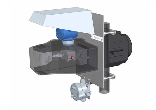
The contact heated enclosure system utilizes an insulated mounting plate that functions as the centre of the structure for the system, and is secured tightly to a stand at 2 points. The mounting plate is a machined structure that is designed to accommodate pass through for the tube fittings, heater power and instrument wiring. An instrument manifold is bolted to the mounting plate with the tube fittings for process and drain being accessible from the back of the plate. A self-limiting contact heater is bolted directly to the instrument manifold so that the maximum surface area of the heater is in direct physical contact with the wetted parts. To prevent exposure to the elements either a body enclosure or full enclosure are used. The body enclosure is a small insulated two piece unit that secures to the front of the mounting plate and latches with four cold weather durable clasps. The full enclosure uses a hinge at the top of the larger mounting plate to carry a stainless steel outer shell insulated with rigid polyurethane. In both systems it is recommended to use the isolation kit that is installed at the back of the mounting plate to create an insulated chamber for additional protection of the tube fittings.
• Technical Advantages
Since the contact heated instrument enclosures are specifically designed to address the shortcomings of insulation blankets and traditional enclosures, there are numerous technical advantages. The body enclosure provides similar weight and space savings to an insulation blanket, and a full enclosure will be smaller than a traditional enclosure with similar or lower weight. All components in the system are weatherproof and classified for hazardous area use which means the requirement for a double seal weather proof enclosure (typically NEMA 4 or 4X) is eliminated.
• The contact heater provides greater heat transfer with far lower power consumption than a space heater. Additionally the heater is a universal design that will accept power supplies from 100 to 300 volts and 50 to 60 Hz.
o For milder climates i.e. -20°C a 29W self-limiting heater can be used for both body and full enclosure applications. The 29W heater meets the requirement for a T4 hazardous area specification, while a 48W heater will meet the requirements for a T3 area. The 48W heater when combined with a body enclosure is capable of maintaining freeze protection of an instrument at -45°C and has been proven in environmental chamber testing.
o The 48W self-limiting heater when combined with a full enclosure is capable of maintaining freeze protection at -60°C and has also been proven through environmental chamber testing
o By using the self-limiting contact heater, the need to maintain a specific air temperature within the enclosure is eliminated, therefore eliminating the need for an air temperature thermostat, and removing a potentially problematic component. The self- limiting heater ensures a very stable operating temperature for the sensor of the transmitter.
o The direct metal to metal contact of the heater ensures that the maximum amount of heat possible is transferred into the metal of the manifold and through to the instrument sensor as well as the tube fittings.
o In many typical installation there is an extreme risk of a cold point where the tubing bundle enters the enclosure and the heat trace is no longer in full contact with the tubing. The use of another standard component called an isolation kit prevents exposure of this area to cold air and allows the heat to be maintained at this point.
o With the use of the contact heater, if maintenance is required on a transmitter an enclosure can be opened in cold weather situation without losing all heat transfer, whereas when using a traditional system all heat is immediately lost as soon as the air is released and the risk of freezing during maintenance becomes far greater. Additionally there is increased risk of freezing after completion of maintenance as the air inside the enclosure still needs to be completely reheated before the system is correctly operating again, the contact heater eliminates this risk.
• Because of the standardization of components and design the temperature protection can be verified through testing to ensure maximum reliability for the end user. Manifolds of any valve configuration can be installed in this system with no risk of changing the temperature capabilities.
• When using a body enclosure it will be noted that the electronics housing of the transmitter remains exposed to the elements. The advantage of doing this is that the electronics are not exposed to increased temperature as they would inside a full or traditional enclosure. While the smaller heater mitigates this inside a full enclosure, it is best for the MTBF time of a transmitter to have the electronics remain as cool as possible.
• In both the body and full enclosure designs the threaded connections and tube fittings are all outside of the enclosure which can allow for an end user to declassify the inside of an enclosure from a Zone 1 to a Zone 2 atmosphere, which simplifies installation.
• Both the body and full enclosure are also designed to prevent the collection of any liquids. With the potential leak points outside the risk of a process leak inside an enclosure is very minimal, and with a very small drain located in the sloped underside any condensation will be allowed to escape while maintaining the required temperature.
• Both the body enclosure and full enclosure systems will contain a layer of insulation which is typically rigid polyurethane. By itself, Polyurethane is a very efficient insulator but in addition the fact that the air inside is not being depended upon as the heat transfer medium it will also act as a secondary insulation. Much in the way that building construction uses double or triple pane windows to increase the energy efficiency of a home, the trapped air further increases the systems efficiency by not transferring any significant amount of heat to the surface of the enclosure which in the case of a traditional enclosure will act as a heat sink to the outside air.
• Accessibility inside an enclosure has always been a problem due to the number and size of components inside. By using the mounting plate and contact heater the components removed from inside include; the inner stand, secondary mounting bracket, tube fittings, thermostat and junction box. The heater also has a significantly smaller footprint and is mounted in way which makes the risk of contact with skin very insignificant.
• Transmitters equipped with remote seals are also often required to be installed inside an enclosure. Traditionally this is extremely difficult and compromised the enclosure greatly due to the need to cut a hole large enough to fit a flanged diaphragm seal through the wall of an enclosure. Because of the split design of a body enclosure only one or two small exits for the capillaries are required resulting in a negligible impact to the system. In the case of a full enclosure the mounting plate and cover are changed to a slightly different design that uses a split plate that can be removed allowing the diaphragm set through the opening. The split plate is then reinstalled and fit tightly around the capillary with grommets. The resulting system still allows the use of standard components and preserves all of the aforementioned advantages of an engineered solution.
• Technical Disadvantages
For the purposes of installing standard pressure transmitters, technical disadvantages are either virtually non-existent or are mitigated by changing from one enclosure to another.
• The use of a body enclosure leaves the electronics housing of a transmitter exposed to the elements. This is generally not a problem as most transmitter manufacturers use a -50°C design specification. However if a display is to be maintained then the cold temperature will be a problem, and the full enclosure should be used in its place.
• While a rating of -45°C is more than enough to satisfy most project requirements, extreme temperatures are becoming more of a concern every day and at millions of dollars cost from a potential shutdown any risks should be mitigated. If any transmitter manufacturer has not certified their transmitters for use to -50°C or there is even a slight risk of temperature exposure below -45°C it would be best to use a full enclosure.
• In some instances enclosures are used to eliminate the risk of transmitter damage from falling debris such as ice. If this is a risk it is not recommended to use a body enclosure as the electronics can still be damaged, however the solution is to use the full enclosure.
• Space and height requirements are very often a concern for modular fabrication. In the event that height limits are imposed the lift up design of both the contact heated full enclosure or traditional enclosures can be a concern. The solution is to change to either a body enclosure, or a full enclosure ordered with a fully removable cover.
• Commercial Advantages
There are numerous commercial advantages to using contact heated instrument enclosures. They include reductions in cost at all stages of engineering and construction resulting in at least a 30% cost reduction to the project. There are also many long term benefits for the site from a total cost of ownership perspective in reliability and power consumption.
• From an engineering perspective the clearest advantage of using contact heated enclosures is the reduction in time requirements. The use of proven standardized components and designs mean that any engineer can simply specify what type of manifold they require (i.e. 2,3,4 or 5 valve) the transmitter manufacturer and temperature specification. The required enclosure components are selected based on these criteria, and a set of arrangement drawings can be issued very quickly and at no additional charge.
• The ready-made set of drawing will include all components including tube fittings, nuts and bolts as well as electrical cable or conduit components. The drawing can then be issued to any sub- contractors or package unit vendors with each arrangement specified on the P&ID to ensure consistency
• The standardization also allows for the majority of the build process to be handled at an indoor manufacturing facility. Typically the enclosure/manifold supplier will receive the transmitters from the EPC or transmitter vendor as a free issue. They will then do a complete buildup of the entire system to the point where the on-site team should only have to connect power wiring, transmitter communication wiring, and tubing lines.
o Because of the standardized components there is little to no special fitting required which can allow the assembly team to increase production from as few as 5 complete assemblies to as many as 50 in a day.
• Once a completed assembly is received on site, the labour time to install it is significantly shorter. There is no requirement to cut holes through the outer wall and install weather seals and the difficulties in cutting and fitting short lengths of tubing inside a tight space are eliminated. The only piece requiring any cutting will be the isolation kit which is the final component and is cut to fit around the completed components rather than fitting component inside a cut piece. The time savings are often easily as much as 8 man hours per enclosure and can be significantly higher depending on the complexity of the installation (i.e. differential vs static pressure)
• The long term advantages from a maintenance perspective are difficult to calculate because of the diversity of services that instruments are used in, as well as the site requirements for calibration frequency. However due to the fact that process access is unrestricted the time required to work on any transmitter will be significantly reduced.
• With the costs of power ever increasing the ability to reduce consumption is more and more important. The lower wattage of the contact heater is prime example of a way to reduce costs. For example:
o The most common solution for a pressure transmitter with LCD readout is a traditional enclosure having an insulation layer inside and a thermostatic controlled heater ranging from 200 to 500 Watts depending on the volume of the enclosure. For a plant holding 2000 of these hookups the lowest average energy consumption for only the instruments if temperatures drop below zero is 2000 x 200 Watts = 400kWh x 24 hr. = 9.6 Mega Watts/day x 250 days (average days below zero) = 2.4 Giga Watts/yr. This staggering amount of energy is excluding all line and vessel tracing and only to keep the instruments above freezing
o Installing the instrument assembly into a contact heated full enclosure only 48 Watts using the same example calculation as above the power needed is 2000 x 48 Watts = 96kWh x 24 hr. = 2.3 Mega Watts/day x 250 days (average days below zero) = 576 Mega Watts/yr. which is a power saving of approximately 300%.
• Commercial Disadvantages
Commercial disadvantages from the use of contact heated enclosures are truly minimal. For any standard application there is no solution that can rival the overall cost effectiveness of contact heated enclosures. However there may be certain applications where standard components cannot be used.
• In the event that an enclosure system is required to contain a multi component system such as sampling and regulation it becomes impossible to use standardized components. There will be no manifold per-se to carry a contact heater, and many different configurations of components could be required for a single project. In this case a traditional enclosure is often the only viable solution other than to move the entire assembly indoors.
• The use of a contact heater requires a manifold specifically designed to be assembled with it. The cost of this manifold will always be competitive with any high quality manufacturer despite small design differences. The only time this can be a disadvantage is where the service only requires a very low cost manifold. However choosing a low cost manifold will require the use a different enclosure system which will still allow the contact heated system to be more cost effective.
5. Conclusions
Soft packs and traditional enclosures have proven themselves to be useful tools for prevention of instrumentation freeze for more than 40 years; however we need to recognize that technology does change. In certain circumstances a soft pack or traditional enclosure may be the only option to prevent instrumentation freeze up and unplanned and expensive downtime. For example large items such as valves cannot be enclosed in any sort of pre-manufactured rigid enclosure, and therefore a soft pack is the only viable option. Small sample systems cannot be protected by a soft pack and are impractical for the use of contact heated enclosures.
Pressure instrumentation using manifolds is undoubtedly best protected using a contact heated body or full enclosure. The design simplicity and commercial practicality make it unquestionably the best solution for new installations and retrofit applications.
With new developments in soft pack technology that have entrenched heat tracing, or with “universal mount” systems being developed for traditional enclosures, proponents of these systems can argue in favour of their use. However no number of tiny innovations can take the place of using a engineered system that with the sole purpose of preventing pressure instruments from freezing in cold weather.
As the need for construction in increasingly harsher climates grows, the need for more reliable and efficient winterization systems increases as well.
In conclusion, except for small specific exceptions there is no better way to protect pressure instruments from freezing than to use a contact heated enclosure system. From all technical and commercial perspectives the advantages and risk reduction cannot be matched by any other commercially available system.
-
Navigation
- Home
- Suppliers & System Integrators
- Products & Services
- Brands
- Advertise
- Conversion Tables
- Articles/Case Studies
- Links
- Contact Us
External Links
-
All contents copyright of ISA
© 1995-2026. All rights reserved. -