Articles / Case Studies
-
-
The Advantages and Disadvantages of Close Coupled versus Remote style Hookups
 1.0 Introduction
Throughout the years pressure and differential pressure measurements are important parameters for process control in chemical and petrochemical installations. Together with temperature a variety of values can be derived from these measurements, such as flow, and level.
Also born from history is the way an installation used to be designed by engineers, where the disciplines of mechanical piping and instrumentation and control used to be strictly separated from each other, only providing interconnection between process and measurements.
This separation of disciplines had a few reasons for existing in the first place, being the sequence an installation has to be build, where mechanical construction also is done before instrumentation and control components can be installed.
A second reason is the specialist approach of the disciplines where mechanical and piping engineers often are educated in different skills then instrumentation and control engineers.
Throughout the years of installation engineering and building this segregation of disciplines was logical and accepted by everyone.
Due to a certain building sequence the way instruments are hooked up to the process was limited to the options left by the mechanical piping construction and nozzles.
This often resulted in a remote type of hooking up pressure instrument to process lines and vessels, where the actual instrument was placed in such a way that it was easy to operate and calibrate by the operators.
The generic way of remote instrument hook‐up’s is always a string of closing elements which run from the primary process connection nozzle, followed by one or two impulse lines, often made from a high grade stainless steel and closed by a set of valves or manifold to enable segregation of the instrument from the process on an operator level.
Also if a manifold is used the operator must be able to calibrate, test and drain the instrument without removing it from it's process connection. (vent/equalise).
Older transmitters also need more calibrations then new generations, which are virtually maintenance free and do not require manual attention from operators.
To ensure that the first process valve, also called the root valve, which is the last line of defence has a certain reliability factor, often this is a combination of two separate valves behind each other with a bleed valve in between.
The bleed function gives the operator the option to test the first valve on leakage by closing both isolation valves and opening the bleed.
The way these measurements are fitted in the installation throughout the years had certain advantages, but certainly also disadvantages over newer technologies which are being developed recently, such as closed coupled measurement hook‐up’s.
Both types of hooking up instrument to the process will be discussed in detail in the following chapters.
2.0 Traditional remote hook‐up’s
To connect a pressure transmitter to the process the traditional method was by using the following components to make the connection:
• A double block & bleed fire safe process valve construction directly onto the process nozzle.
• One or Two stainless steel impulse lines running from the process valves to the operator level where the instrument is mounted.
• A mechanical rack or support brackets holding the impulse lines.
• A mechanical construction holding either the manifold or the transmitter.
Dependent on the process and/or the environmental conditions the complete construction is traced using steam lines or electrical tracing and is insulated and protected against mechanical disruption of the often soft insulation materials using aluminium shells.
The advantages and disadvantages which are mentioned in the following chapters are split into technical/operational and commercial issues.
2.1 Technical/Operational advantages
Having an instrument fitted on operator level has certain advantages, such as:
• Easy to reach for calibration, maintenance repair and replacement.
• No need for remote indicators as integrated indicators can be read directly.
• Leakages can be visually detected in an early stage.
If you place the advantages in their current perspective of high‐tech and maintenance free instruments a few of the advantages are somewhat outdated, certainly if compared with the disadvantages of remote installation.
2.2 Technical/Operational disadvantages
Depending on process and environmental conditions the remote installation certainly has technical and operational disadvantages, such as:
• Long impulse lines which influence the measurement due temperature fluctuations.
• Clogging of impulse lines due to "cold spots" or restricted diameter of the impulse lines. Chloride Stress corrosion cracking, which occurs if Stainless Steel impulse lines are used at temperatures over 50°C and chloride is present.
• A multitude of possible leakage points between process and instrument due to the amount of connection interfaces.
• High power consumption for winterizing and/or process heating.
• Large space used for instrument enclosure if heated.
Especially impulse lines are a major source of problems in relation to clocking, blockage and corrosion in remote pressure hook‐up’s.
As the impulse line heating is often not precisely controlled, but merely limited within the specification of the tracing tape and insulation value, a large deviation in temperature will occur if the ambient temperature fluctuates during a day‐night cycle and summer I winter conditions. This can cause blocking and corrosion problems when temperatures will rise on the impulse lines causing some products to crystallize, increase sealing (like H2S) or become more corrosive then at optimal process temperatures.
Crystallizing and sealing products will cause clogging of the impulse lines increasing the reaction time
of the measurement dramatically or even block the lines completely holding the instrument on a steady value which is not related to current process values anymore.
Excessive rises in line temperature can also cause boiling of the process liquid inside the lines causing large measurement offsets and possible dangerous situations.
The amount of leakage points becomes more and more a source of attention for plant operators as leakage often causes secondary damage to the installation, the instruments and can be potentially dangerous to personnel and environment.
Due to the insulation on the lines and valves leakage is often not detected at all or only detected after extended damages is already caused by it.
All in all leakage is a bad thing both technically, environmentally as well as commercially.
2.3 Commercial advantages
As the complete hook‐up is built from separate components only one commercial advantage can be mentioned, such as:
• Lower price per component
In case of failure of one specific component the bare cost for replacement parts can be slightly lower than other measuring technologies such as close coupled.
2.4 Commercial disadvantages
As suspected from the previous chapter, the commercial disadvantages outnumber the advantaged by large numbers.
We can split the disadvantages in two categories, being installation costs and operational costs for this kind of hook‐up.
Commercial disadvantages during installation are:
• Total cost of materials is very high (manifold, impulse lines plus support, insulation, tracing, two large root valves with a bleed)
• Total installation cost is very high (labour intensive and complicated and time consuming installation)
Commercial disadvantages during operation are:
• Cost related to leakages (repairs, replacement, environmental costs, medical costs and worse)
• Cost related to clogging, sealing and blockage (plant stops and trips, costs for cleaning impulse lines, or replacement of impulse Iines.)
• Cost related to corrosion (see leakage, plus replacement of impulse lines and insulation)
• Cost related to heating (large power consumption due to number of components and line length)
Of course if all incidents should occur at the same time this can be categorized as a doom scenario, but experience learns that any of the above will happen in random order and often simultaneously, making operational costs, which are continuous costs, even more critical than one time installation costs. Especially the virtually uncontrolled tracing temperature is a proven nightmare for operators running plants where sealing or crystallizing products are causing continuous problems.
Alternative manners of hooking up instruments should be considered seriously to reduce both the commercial and technical disadvantages of traditional remote installation of transmitters drastically.
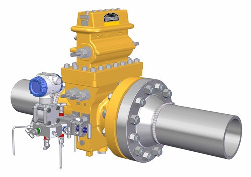
3.0 Close Coupled hook‐up’s (a.k.a. Direct Mounted hook‐up’s)
As a result of before mentioned continuing technical problems and commercial costs involved both the industry and the valve manufacturers worked closely together to develop alternative measuring methods as well as alternative ways of connection and installing instruments into a process installation. One technology which has become proven to solve the majority of technical and commercial disadvantages is called Close Coup led technique, also known as Direct mounted instruments.
The objective of this installation technique is to install the pressure instrument as close as possible to the process nozzle, preferably directly onto it.
The product used to accomplish this should also replace the primary process valve, but keep the same safety aspects of the old way of installing.
This implied that a Double Block&Bleed function had to be present, where the first valve, the root valve, also had to comply to the British Standard Fire Safe rules. (BS6755 part 2).
The result must be a working pressure measurement hook‐up with both process valve as well as manifold functionality, but without the costs and operational problems known from remote hook‐up’s. The challenge was to find a perfect compromise between two worlds, being mechanical piping and instrumentation and control, who both have very different sets of design r ules and criteria.
That this technique is becoming more and more accepted within the industry and has resulted in approvals from Shell, NAM, TotalFinaElf and many more for the existing products from Multi Instruments and is supported by an installed base of over 5000 units in the last two years alone. To make a fair comparison we will sum up the same set of technical/operational and commercial advantages and disadvantages for this installation technique.
3.1 Technical Operational advantages
One of the incentives for developing this technique was to eliminate the most common technical and operational problems which occur in a traditional remote hook‐up.
The technical and operation advantages can be summed up like:
• No impulse lines (meaning no volume to heat, no cold spots, no clogging, no temperature influence)
• No construction needed for impulse lines, saving space.
• No heating and insulation needed for impulse lines, saving energy demand for heating/tracing.
• Virtually no volume (the only volume is the close coupled monoflange manifold volume itself) Compact installation (only the space needed on the process nozzle)
• Only two leakage points on interfaces (process/valve and valve/instrument)
• No cold spots due to close proximity to the main process line and very compact heating options.
• Accurate dimensioning of heating capacity possible due to limited amount of junctions,
• temperature bridges and an enclosure with a very dense and constant insulation capacity.
• No sealing or corrosion problems due to close proximity to process temperature and less fluctuations in instrument and valve temperature.
Summing up the most important features the result is a super compact, low volume and fast responding pressure hook‐up, with virtually no leakage points and no complex installation.
Although this sounds too good to be true, there are a few disadvantages for this technique, described in the following chapter.
3.2 Technical/Operational disadvantages
To avoid over excitement on this technique it is only fair to mention the disadvantages of close coup led technology as well, which are:
• Cannot be used on applications over 120°C (due to limitation ofthe instrument)
• Cannot be used on cryogenic applications (same reason as hot applications)
• Cannot be used on applications with large solids (due to limited drilling size)
• No direct eye contact between instrument and operator (often installed on top of a piping bridge), so remote indicators are needed for indication.
• Instrument and application needs to be maintenance friendly or free as access to the instrument is sometimes more difficult.
Considering the disadvantages mentioned close coup led technology is a technically good solution for approximately 70 to 80% of all installed measurements in a plant, causing a huge improvement in performance, maintenance costs and plant integrity and safety.
3.3 Commercial advantages
Due to a large reduction in components and additional support requirements in the installation this technique should account for large savings in both installation and operational costs.
To give an accurate overview of cost savings we will split them again in costs for installation and operational costs.
Cost reductions during installation are:
• The close coupled manifolds replaces the complete root valve construction, impulse lines including supports, tracing and insulation and the traditional manifold assembly.
• Installation time is reduced to minutes per measurements due to a "plug & play" approach.
• Tracing costs are reduced to only the close coupled assembly.
• Insulation costs are virtually eliminated as the close coup led assembly can be supplied with a high grade insulation body enclosure.
• Labour intensive impulse piping installation is eliminated as no impulse piping is required.
• Catwalks and intermediate floors can be eliminated while the complete assembly will be directly onto the piping nozzle.
• Due to the one piece compact design a tremendous amount of space is saved, which is especially cost saving in offshore installations.
Cost reductions during operation could be things like:
• Power consumption for tracing and heating is reduced to a minimum, compared to traditionally traced hook‐up’s, and also power consumption is more constant.
• Leakage problems are reduced to a minimum as only two interfaces per measurement exist.
• Fast response of the measurement due to the direct connection onto the process line and minimal volume can result on more stable and higher quality process output.
• Costs for cleaning and replacing impulse piping are eliminated.
• Failure diagnostics costs are minimal as the operator only has to concentrate on a one piece measurement without external piping or difficult to see/reach components.
3.4 Commercial disadvantages
With a huge amount of commercial advantages, there are a few commercial disadvantages to mention after all, being:
• As this technology requires maintenance free transmitters, these could be slightly more expensive then low cost instruments.
• The ability to reach the instrument could be slightly more difficult, which could increase cost for rental cr anes during full inspection during a plant stop, however this equipment is normally available during large maintenance stops.
• Due to the fact that close coup led manifolds also act as primary process valves they should be ordered (together with the transmitters) earlier in the project due to pressure testing of the process piping, which can disrupt the cash flow in traditionally calculated projects.
• As instruments have to be installed at an earlier stage of the project, extra costs for replacement due to damage caused during construction could be an issue.
• Replacement of a close coupled valve is more expensive then replacing a single component in a traditional remote hook‐up.
• In a worst case situation a heavily damaged close coup led manifold could require a plant stop for replacement, however this is also the case for traditional root valve replacement.
• Due to the extra weight stress on the process nozzle a slightly heavier design could increase the cost for this nozzle slightly. (a good solution for extra strength is using long welding neck flanges and smaller flange sizes as the usual 2", which is not necessary for measurement purposes)
4.0 Closing Arguments
As with all new technologies a lot of it's success depends on the level of acceptance by the industry. Depending on the end users instrumentation philosophy some aversion is detected on the concept op replacing the good old root valves by a physically tiny looking OS&Y needle valve construction. Another point of argument will remain the choice of base materials, where the primary discussion is the invisible interface between piping rules and instrumentation rules.
Best example is the discussion on the process side flange, which has to connect to either ASME or DIN design counter flanges and where ASTM rules restrict the use of certain base materials to full forgings, based on the required strength for industry standard flange thicknesses, where instrumentation valve design allows the use of materials like warm rolled and forged barstock or castings.
However, arguing in favour of instrumentation rules, you will see that other then the facing and bolt hole sizes the thickness of a monoflange manifold exceeds the required flange thickness three or more times. The same argument stands for the minimum requirements of wall thickness for the manifold as well as the "flange" part of it, which are in conflict again.
In all cases there are a number of conflicts in interest between these two disciplines, mainly based on their objectives for the installation.
The final design and choice of base materials will be a decision made by and based on the requirements from the end user, but in any case the designs will fulfil the mechanical strength criteria required by both piping and instrumentation rules.
For all manifold designs a strength calculation is made together with isometric drilling overviews to ensure that minimal wall requirements are met and supersede the calculated values with a safety factor of 2 or more.
The variety of customer wishes has resulted in a large variety in designs for close coupled technology. As the first large scale experiences are being collected at end user installations with various purposes rating from natural gas to refinery applications in both on‐ and offshore it looks that this new installation technology is gaining acceptance in any form rapidly.
Adapting to customer wishes and demands will increase the interest for this technology even further and this will also bring down the costs for production significantly as larger volumes can be produced at once.
Flexibility is the keyword to success for this technology, both from a manufacturers as well as the end users point of view.
The result should always be a virtually perfect design meeting requirements from the end user and also keeps the manufacturer commercially interested in producing and expanding the range of products. Up until now, these criteria where always met to full satisfaction of all parties involved.
-
Navigation
- Home
- Suppliers & System Integrators
- Products & Services
- Brands
- Advertise
- Conversion Tables
- Articles/Case Studies
- Links
- Contact Us
External Links
-
All contents copyright of ISA
© 1995-2026. All rights reserved. -